Copper Weld
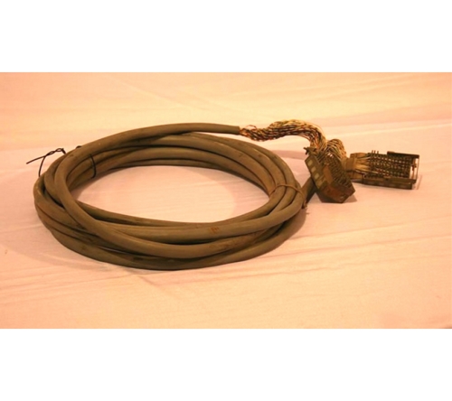
Alexander Graham Bell invented the telephone over 100 years ago. At first, the telephone lines were separate lines that connected pairs of telephones. The telephone lines were single grounded wires made of iron or steel. Some wires were galvanized for corrosion resistance, but corrosion problems were never the less prevalent. The lines were single grounded wires and they were inherently noisy. Phosphor bronze wires and compound copper steel wires were made in attempts to decrease the noise in the lines. The benefits of using copper conducting wire were known, but the technology was not available to make a copper wire strong enough for an overhead wire. Then in 1877 Thomas Doolittle developed the process for hard drawn copper wire in the Naugatuck Valley of Connecticut. He had soft, annealed copper wire drawn through a series of dies in order to increase its tensile strength. The hard drawn copper wire was strong enough for overhead wires and copper took over the telephone wire market. In 1884 an experimental long distance telephone line made of copper was set up between Boston and New York. Thus, copper weld wire has been utilized and relied upon for years as a strong, non-rusting, efficient grounding conductor which combines the strength of steel with the conductivity and corrosion resistance of copper. These properties make it ideal for many utility, telecommunication, and general industry applications.
Telephone Cable
A telephone cable is called Category 3 or CAT3. It has 4 wires inside of the cable sleeve, 2 are used for data, one for power and one for ground. Though, Alexander Graham Bell invented the telephone over 100 years ago. The first telephone cable line was set up in Boston in 1877. It connected the home of Charles Williams Jr. in Somerville MA with his Boston office. In Nigeria, the lines came into existence with the arrival of the telephone especially in the homes and offices of the then colonial officers. In most cases, two copper wires (tip and ring) for each telephone line run from a home or other small building to a local telephone exchange. The wires between the junction box and the exchange are known as the local loop, and the network of wires going to an exchange, the access network.
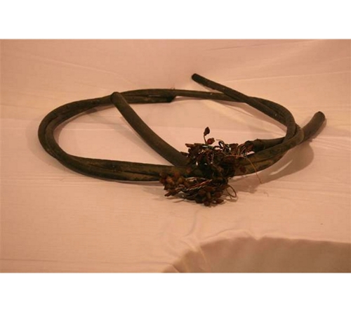
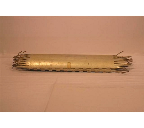
Paper Core Unit Paper Insulated
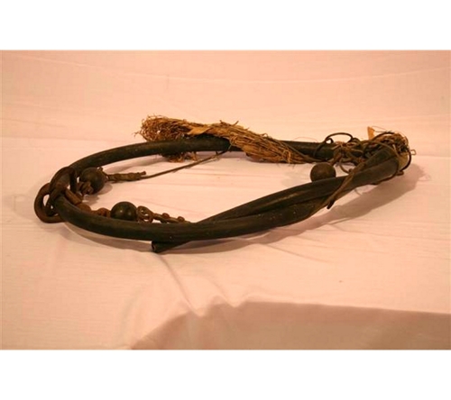
Telephone cables were employed for aerial, underwater and underground use around 1879. Early cables were single grounded wires followed by metallic circuits lines after their development. However, there was need for improvement; this led to the development of paper insulated dry core cable (which served as conductor). The dry core cables were successful because the lead tin alloy sheathing now provided adequate water proofing. By 1891 dry core, paper insulated cable was the standard. The size of the conductor and the electrostatic capacity requirement were further reduced and greatly decreased the noise in the lines.
By the late 1890's telephone and electric power cables were laid underground in conduits made of creosoted wood, and by 1891 dry core, paper insulated cable was the standard. The size of the conductor and the electrostatic capacity requirement were further reduced and greatly decreased the noise in the lines.
Binding Wire
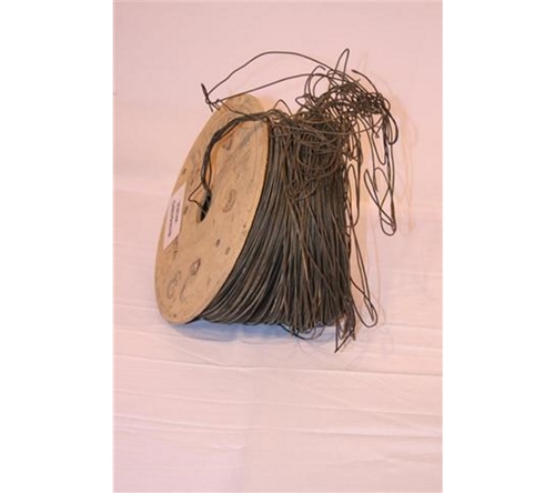
This is a tapered fibre optic distribution cable that includes a plurality of drop cables having at least one predetermined breakout location where a drop cable is withdrawn from the tapered distribution cable. The drop cables are bound together to form the tapered fibre optic distribution cable by binding members or helical winding. Each drop cable contains a plurality of optical fibres which may be reconnectorized according to a user's preferences. It was invented by Brian Herbst and assigned to AFL Telecommunications LLC. The filing in US was on August 8, 2006. The Patent number is: 7590320.
Clipper
A circuit or device that limits the instantaneous output signal amplitude to a predetermined maximum value, regardless of the amplitude of the input signal. This was introduced in the 1950s.
Universal Closure
A UC is a type of closure for tightening Optic Fibre Cables and for Splicing of cables. It has been in use from 1993 to date.
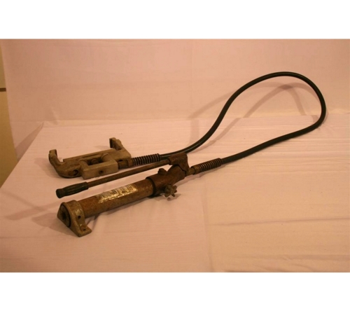
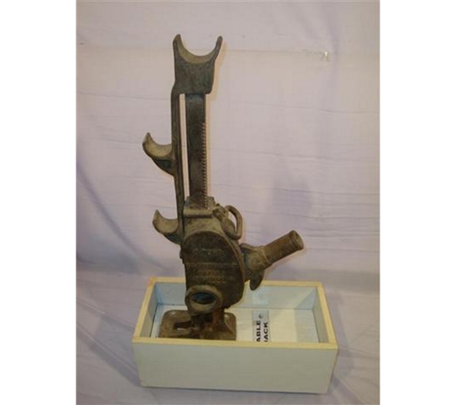
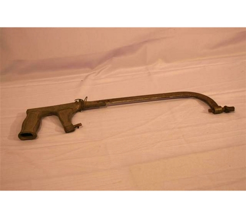
Cable Jack
(a) To understand a Cable Jack we first of all explain a Telecom Cable as: Cables primarily designed for the interconnection of telephone equipment which is installed indoors. Telecom UTP cables are terminated with standard connectors (plugs and jacks) or punchdowns. Therefore, a Cable Jack can be explained as a telephone cable plug that has a type of male connector used to connect a telephone to the telephone wiring in a home or business, and in turn to a local telephone network. It is inserted into its female counterpart, a telephone "jack", commonly affixed to a wall or baseboard. It is a connector of outgoing lines and bulk circuit. Modern Telephone Cable jacks were introduced in 1985.
(b) Cable Jacks: Cable jacks are used to lift, support and stabilise low and high voltage cable drums to enable efficient cable laying and pulling for low and high voltage cables - this includes hydraulic cable jacks, screw cable jacks and cable jack towers for lifting cable drum weights up to 30 tonnes. Standard hydraulic cable drum jacks lift 3 tonne, 6 tonne and 10 tonne weights. Registered jacks were introduced by the Bell System under a 1976 FCC order ending the use of protective couplers provided exclusively by the telephone company. The new modular jacks replaced earlier, bulkier connectors.
Cable Clamp
In the early 1900s, Cable clamps were used to make cable installation easier, and they provide protection from the damage that high winds inflict upon improperly fastened cables; damage that may lead to increased reflection due to mechanical stress.
Cable Roller
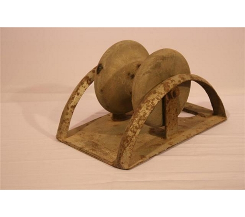
This is used to release the telecommunication cable and the power cable. It has been in use since the early 1900.
Cable Bearer
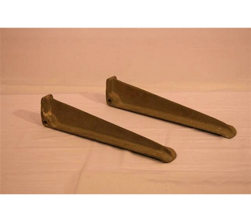
These are among the different types of cable bearers used from the early 1990s among which are:
a. Bracket Cable Bearer: A Bracket Cable Bearers are fixed to the Cable Bearer Wall Type by means of the Pins Locking Cable Bearer. They are made of galvanised cast iron and are designed to support all types of multicore cables and closures.
b. Cable Bearer Wall Type: Wall Type is used for supporting Cables in manholes and Joint Boxes. They are fixed to the wall of the chamber/Joint Box to accommodate the Bracket Cable Bearers.
Pins Locking Cable Bearer: Used to fix Brackets Cable Bearer to Cable Bearer Wall Type.
3M Better Buery
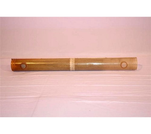
This is used in the buried compound compression closure method which forces the encapsulant up the cable core to stop water ingress. The product is simple to install, comes with the spacer web and plastic wrap and is used to hold and force the encapsulant. The product which came into use in the 1980s is offered in different sizes to cover various cable ranges and can be easily extended and bricked.
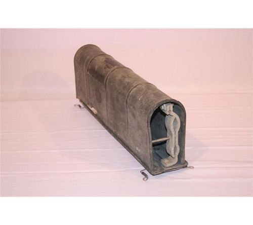
Hale Split Splice Case
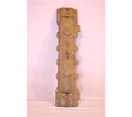
This is a brand of Split Splice Case Product. It is an airtight, watertight, self-contained housing for buried communication lines, such as telephone lines comprising a main cable and service wires. This was used in the 1970s to date.
Underground Cable Roller
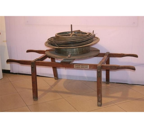
Underground cable roller came into use in the early 20th century and it is used for installation of underground power cable or communication cables. There are different types of rollers for installation of communication or power cable in the trench, some of which are: Trench Roller, Twin Link Corner Roller, Trench Feed Roller Set, Manhole Quadrant Roller, Duct Entry Rollers and Cable Duct Protection. It is advisable that Cable rollers should always be used when pulling cables.
Wrap Around Sleeve for Raychem Closure
This is a closure for a telecommunications splice case comprising of a wraparound sleeve secured for example by a rail and channel closure. It is a recoverable polymeric article for use as a wraparound sleeve, having a first upstanding rail adjacent one edge thereof, and a second upstanding rail spaced from another edge such that the portion of material between the second rail and the other edge is a flap. It was invented by Dexter C. Tight, Jr. in 1982 when the Patent number: 4436566 were filed in the US. The original assignee is: Raychem Corporation.
Porcelain Glass
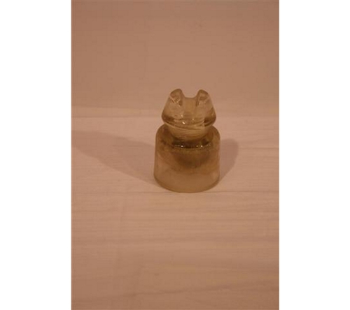
Porcelain Glass is used as an insulator and was first produced in the 1850's for use with telegraph lines. As technology developed insulators were needed for telephone lines, electric power lines, and other applications.
Porcelain Bakelite
Porcelain Bakelite is used on everything from power lines to telephone and telegraph lines insulators. The Bakelite is made of Phenol formaldehyde. It was introduced in the early 1900s
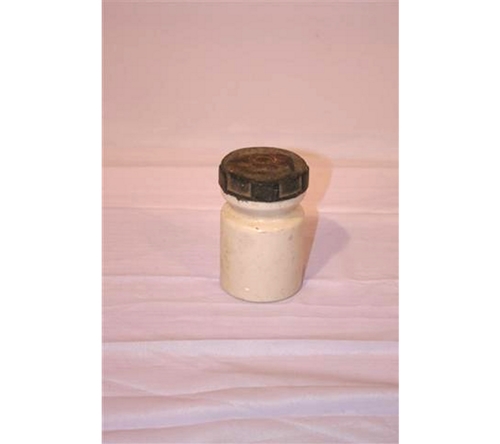
Porcelain Insulator
Porcelain Insulator is an insulator with the skirt made by a ceramic process. Wires are strung between poles and insulators were used to keep the wires away from the poles. Insulators are at the root of a technology that is prevalent throughout the world today, although many people do not know what they are. The need for insulators began in the 1840s in response to the developing use of electricity and new forms of telecommunication. This was introduced in the late 1860s when Graham Bell invented the telephone.
Spindle W Type
This has W-shape and it is used as a rotary spindle structure applied in housing, which includes two spindle lugs having a suspended resilient butt joint respectively. When a spindle rod is fit in the spindle lugs, both end faces of the spindle rod bear against the resilient butt joints, so that the resilient butt joints are forced to expand outwards till a pivot hole of the spindle rod is snapped with protruding walls of the spindle lugs, and thus, the spindle rod is freely rotationally connected to the spindle lugs. It was used in late 1860s
Spindle U Type
This has U-shape and it is used as a rotary spindle structure includes two spindle lugs having a suspended resilient butt joint respectively. It was put into use in late 1860s
Spindle J Type
This has J-shape and it is used as a rotary spindle structure applied in housing is provided, which includes two spindle lugs having a suspended resilient butt joint respectively. Furthermore, a pair of reinforcing pads is used to bear against the resilient butt joints to enhance the joining strength between the spindle lugs and the spindle rod. Like the W Spindle type, it was used from 1860s to date.
Spindle Straight Type
This is a straight type/ shape and it is used as a rotary spindle structure applied in housing is provided, which includes two spindle lugs having a suspended resilient butt joint respectively. Used when telephone cable were introduced in late 1860s.
Pole Cap

This is a self-locking utility pole cap which is made from a tough glass-filled polyester, which is a durable material designed to withstand aging and weathering in an exposed weather. A protective pole cap for installation onto the top of a utility pole has a downwardly-open, cup-shaped body formed with radially inwardly and upwardly projecting, resiliently deflectable finger-shaped projections for releasable gripping engagement with the top end portion of a pole. This was introduced in 1453.
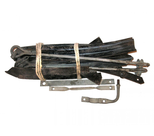
Pole Arm Steel Type
This is used for suspending cables at a distance from the pole. Example is the steel arm bracket which is used with the C4000445 (steel arm yoke) where the steel arm is not equipped with an end plate. The bracket is made of heat treated aluminium and is complete with a wheel binder. The steel arm bracket serves the same purpose as an end plate to support the yoke assembly. This was introduced in the early 1453.
Telephone Pole Wood
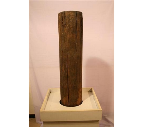
Telephone poles provide the traditional means for stringing telephone lines through cities and neighbourhoods, wood telephone poles have been used since the mid-19th century for telecommunications. As telephone and electric service expanded in the 20th century, poles sprang up across to handle the power needs of the country.
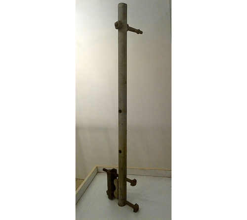
Telephone Pole Metal

As already described above on the wood telephone pole, they provide the traditional means for stringing telephone lines through cities and neighbourhoods, metal telephone poles have become more popular in recent years around 1920s, because they provide a number of benefits over wood telephone poles: Unfortunately, many of the cities in Nigeria today no longer use the analogue telephone since the introduction of the mobile GSM.
Pole Brace
This is used in push pole application where guying is not feasible. Brace adjusts for different pole angles. It is made of Ductile Iron-Hot Dip Galvanized. Pole brace connector brackets will permit an attachment angle up to 90 degrees with the pole. The pole contacting surface is curved with integral teeth for maximum stability and distribution of the load. It was introduced in 1926.
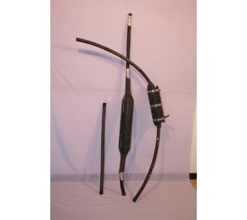
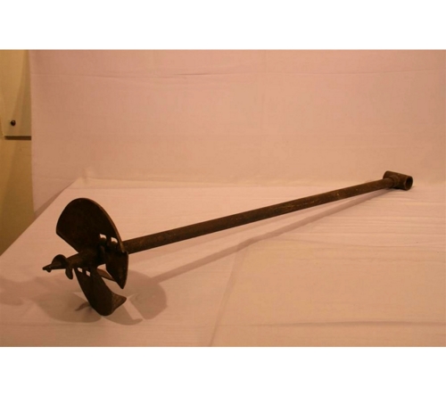
Earth Auger
An auger is a drilling device, or drill bit, that usually includes a rotating helical screw blade called a "flighting" to act as a screw conveyor to remove the drilled out material. The rotation of the blade causes the material to move out of the hole being drilled. An auger used for digging post holes is called an earth auger, soil auger, or mechanized post hole digger. This kind of auger can be a manually turned, handheld device, or powered by an electric motor or internal-combustion engine, possibly attached to a tractor (being provided with power by the tractor engine's power take-off as shown). The ancient Auger was used in 1496.
Lightning or Thunder Arrester
A lightning / Thunder arrester is a device used on telecommunications systems and electrical power systems to protect the insulation and conductors of the system from the damaging effects of lightning. The typical lightning arrester has a high-voltage terminal and a ground terminal. When a lightning surge (or switching surge, which is very similar) travels along the power line to the arrester, the current from the surge is diverted through the arrestor, in most cases to earth.
In telegraphy and telephony, a lightning arrestor is placed where wires enter a structure, preventing damage to electronic instruments within and ensuring the safety of individuals near them. These prevent the flow of the normal power or signal currents to ground, but provide a path over which high-voltage lightning current flows, bypassing the connected equipment. Their purpose is to limit the rise in voltage when a communications or power line is struck by lightning or is near to a lightning strike. If protection fails or is absent, lightning that strikes the electrical system introduces thousands of kilovolts that may damage the transmission lines. In 1752, Benjamin Franklin invented the first Thunder/ Lightning Arrester.
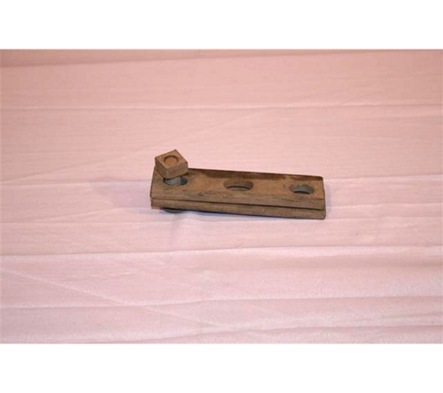
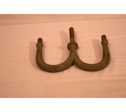
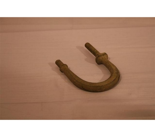
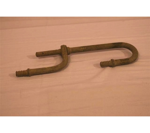
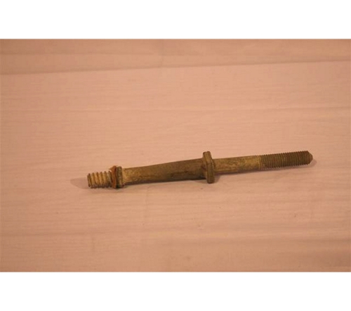
House Hook
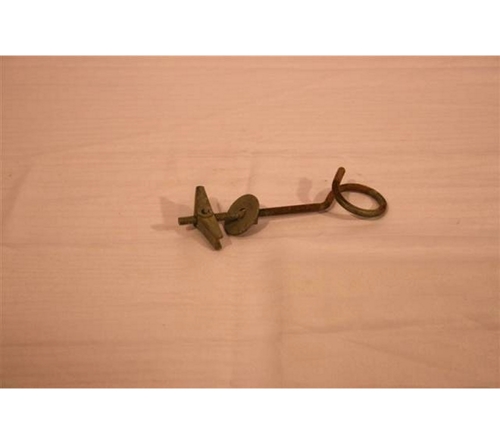
This is used as an attachment to wood or masonry/ house for accepting the bail of drop wire clamps. It keeps guy wire from creeping downward when pole is guyed sharply. Hooks should be used under bolt heads for maximum shear strength. It came into use in 1870.
Bolt Cutter
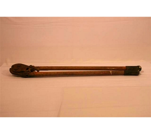
A bolt cutter, sometimes called bolt cropper, is a tool used for cutting bolts, padlocks, chains and wire mesh. The original use for bolt cutters was as the name suggests cutting bolt seals from shipping containers at the delivery point. It typically has long handles and short blades, with compound hinges to maximize leverage and cutting force. The bolt cutter was invented in 1885 by the Swedish blacksmith Jonas Byman, from Tosåsen in Jämtland. Both prototypes are kept preserved in the neighbouring village of Persasen. Jonas Byman, the inventor, died in 1918.
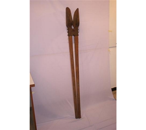
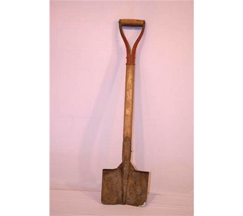
Rabbitting Spade


This is used when digging holes in confined spaces; the slightly dished blade is an ideal for post hole digging. The flat treads provide better grip, increased comfort and protection to the user's feet. Jeremiah Carter, the son of a Blacksmith, Dave Carter, established the hand tools making Company in Highburton, UK in 1740. In 1870 the Carter Shovel was developed for the rapidly expanding coal mining industry, which was fuelling the Industrial Revolution
Spade
A spade is a tool designed primarily for the purpose of digging or removing earth. Early spades were made of riven wood. After the art of metalworking was discovered, spades were made with sharper tips of metal. Before the advent of metal spades manual labour was less efficient at moving earth, with picks being required to break up the soil in addition to a spade for moving the dirt. With a metal tip, a spade can both break and move the earth in most situations, increasing efficiency Jeremiah Carter developed the first spade in 1740.
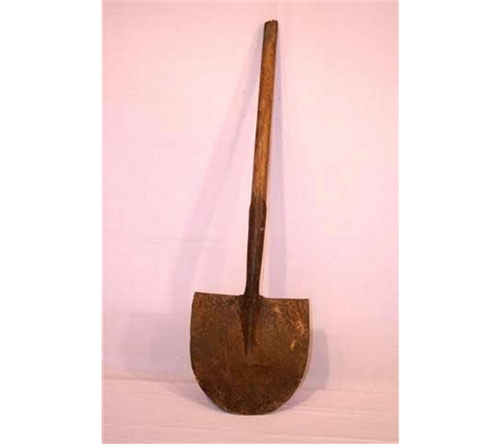
Shovel
A shovel was first used around 1870 and it is a tool for digging, lifting, and moving bulk materials, such as soil, coal, gravel, snow, sand, or ore. Shovels are extremely common tools that are used extensively in agriculture, construction, and gardening. Most shovels are hand tools consisting of a broad blade fixed to a medium-length handle.
Jack Knife
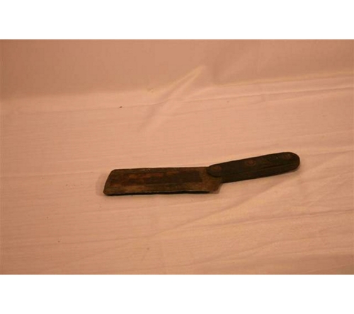
Jack knife is a folding knife with one or more blades that fit inside the handle that can still fit in a pocket. Jack knives are versatile tools, and may be used for anything from opening an envelope, cutting twine, slicing a piece of fruit, etc. The earliest known pocket knives date to at least the early Iron Age. A pocket knife with bone handle was found at Hallstatt, dating to around 600-500 BC.
Hammer

A hammer is a tool meant to pound or delivers an impact to an object through repeated blows. The most common uses are for driving nails, fitting parts, forging metal and breaking up objects. The hand held hammer is an ancient invention no one inventor can be named.
Chain Puller
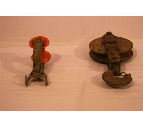
Chain puller or chain pulley or chain hoist is the tool that is used to lift or lower heavy stuff, the rated capacity of these chain puller ranging from 3/4 ton to 6 ton, the lift ranging from 5' to 20', you will always be able to find the right chain puller for your job.
The chain hoist and chain puller sometimes called chain come-a-long, because people can use them to puller heavy objects toward the operator. This tool has been in use since the early 1900s.
Installation Control
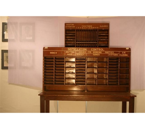
The Installation Control File (inoc6.icf) plays an important role in deployment. It can be used to create customized policy settings prior to deploying the CA TM Agent or you can simply use the default settings. If you use the default settings, you can later create and distribute custom policies using the Threat Management Console. Whether you customize the ICF file or not, your client machines are protected as soon as the CA TM Agent is installed on them.
The Telecommunications Management Network is a protocol model defined by ITU-T for managing open systems in a communications network. It is part of the ITU-T Recommendation series M.3000 and is based on the OSI management specifications in ITU-T Recommendation series X.700. The installation control has been in use since the emergence of analogue telephone in 1860s.
Helmet
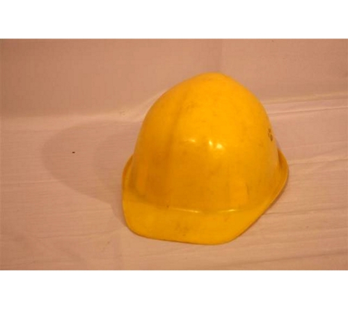
A helmet is a form of protective gear worn on the head to protect it from injuries. The oldest known use of helmets was by Assyrian soldiers in 900BC, who wore thick leather or bronze helmets to protect the head from blunt object and sword blows and arrow strikes in combat. Since the 1990s, most helmets are made from resin or plastic, which may be reinforced with fibres such as aramids.
Plumb
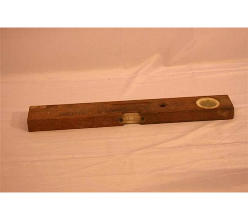
Plumb, a carpentry term meaning a line which is exactly vertical, or perpendicular to a level horizontal plane. It is a weight on the end of a line, used especially by engineers, masons and carpenters to establish a true vertical. A plumb line is a weighted string which when hung from a fixed point and allowed to become motionless indicates perpendicular to level. A Plumb can serve many purposes. The Egyptians invented the plumb bob more than 4000 years ago.
Tool Bag
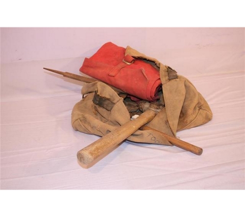
A tool/ equipment carrying bag helps to keep all your tools and accessories organized and easy to retrieve when you need them. Tool bags and tool cases are designed for on-the-job convenience and durability. It also serves as organizers for construction and repair professionals. Tool bags are an ancient invention.
Tape
This is a measuring tape imprinted with clean scales and can easily be wrapped around heavy gauge for the measurement. It is also refers to a strip of long, thin and narrow material, usually rolled up. The first measuring tape was invented by Alvin J. Fellows from New Haven Connecticut. He was granted a patent in 1868.
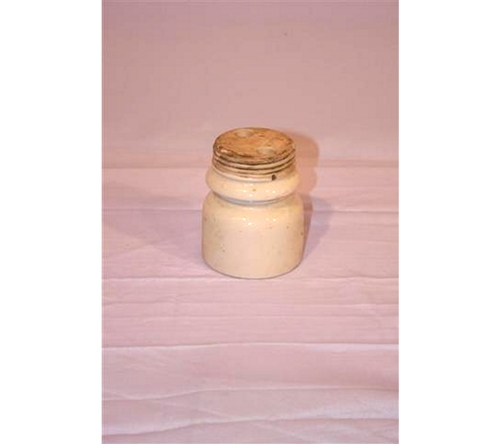
Canister
A system used in 1960s comprising: a container retaining at least one moisture-sensitive article; a canister comprising a desiccant material and an electronic article surveillance radio frequency device (EAS RF); wherein said electronic article surveillance radio frequency device disposed between a label and a release liner, the label applied to the canister, the electronic article surveillance radio frequency device activated to emit an radio frequency signal for detection. The system also has an EAS RF detector which monitors an associated interrogation zone for a signal from the activated EAS RF device thereby activating an alarm.
Power System

This is a system that provides a conversion of a primary alternating current power to direct current voltages required by telecom equipment, and may generate emergency power when the primary alternating current source is interrupted.
Telecommunications DC Power System was invented in the mid-20th century in the United States.
FM Signal Generator
Signal generators and waveform generators are also known variously as function generators, RF and microwave signal generators, pitch generators, arbitrary waveform generators, digital pattern generators or frequency generators are used to test and align all types of transmitters and receivers, to measure frequency and to generate a signal, waveform or noise source. Signal generators can use AC energy, audio frequency (AF) and radio frequency (RF) to function. They are also used to troubleshoot various electronic devices and to measure frequency. The function of a signal generator is to produce alternating current (AC) of the desired frequencies and amplitudes with the necessary modulation for testing or measuring circuits. Hewlett-Packard Company in 1939 sold the first audio-frequency signal generators.
Switch Board
A switchboard (also called a manual exchange) was a device used to connect a group of telephones manually to one another or to an outside connection, within and between telephone exchanges or private branch exchanges (PBXs). The user was typically known as an operator. In 1894, New England Telephone and Telegraph installed the first battery-operated switchboard on January 9 in Lexington, Massachusetts. Public manual exchanges disappeared during the last half of the 20th century, leaving a few PBXs working in offices and hotels as manual branch exchanges. The electromechanical automatic telephone exchange, invented by Almon Strowger in 1888, gradually replaced manual switchboards in central telephone exchanges.
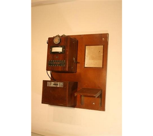
Central Battery Switch Board
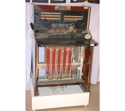
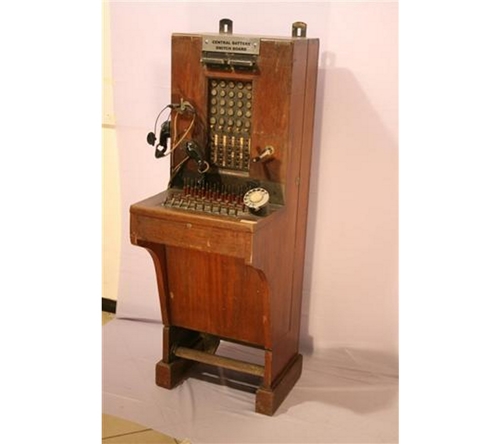
In the year 1888 the common battery system, developed by Hammond V. Hayes, permitted a central battery to supply all telephones on an exchange.
In the first few years of manual telephone service, a single operator could answer all of the calls in the central office and make the necessary connections. Then, in the late 1880s, the "Multiple Switchboard" was invented which allowed multiple operators to answer customer lines and complete calls. Then in the early 1900s, the "Divided-Multiple Switchboard" was placed into service.
Battery
This is a device consisting of one or more electrochemical cells that converts stored chemical energy into electrical energy. Since the invention of the first battery (or "voltaic pile") in 1800 by Alessandro Volta and especially since the technically improved Daniell cell in 1836, batteries have become a common power source for many household and industrial applications. There are two types of batteries: primary batteries (disposable batteries), which are designed to be used once and discarded, and secondary batteries (rechargeable batteries), which are designed to be recharged and used multiple times.
Strowger Step By Step Automatic Exchange
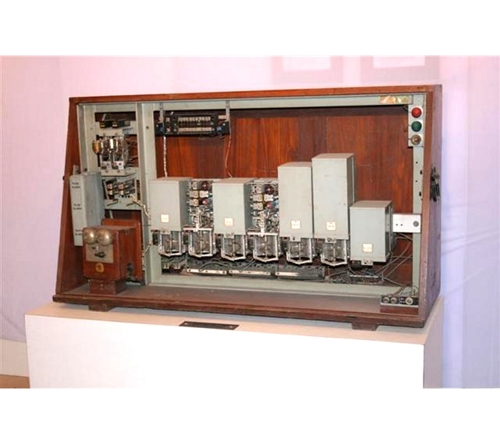
The Strowger switch, also known as Step-by-Step or SXS, is an early electromechanical telephone switching system invented in 1888 by Almon Brown Strowger, an undertaker in Kansas City, Mo, USA. It is a specialized version of a stepping switch. This type is generally known as step-by-step, because each successive dialling of a digit set up another step of the call. The call begins when the caller lifts a telephone handset. This action closes a spring-operated switch in the telephone, completing an electrical circuit. The exchange receives the signal that a caller wishes to dial a number. On receiving the signal, the arm on that line's uniselector begins wiping across a row of contacts. It passes those linked to busy first selectors, stopping only when it finds a contact whose first selector is free.
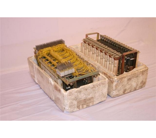
Pentaconta Cross Bar System
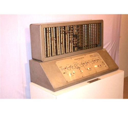
The name Pentaconta System derives from the outlet capacity of its Crossbar Switch: 52, or 50 in round figures. Pentaconta is a Greek for 50 and is also a play on words (conta/ contacts). In electronics, a crossbar switch (also known as cross-point switch, crosspoint switch, or matrix switch) is a switch connecting multiple inputs to multiple outputs in a matrix manner. Originally the term was used literally, for a matrix switch controlled by a grid of crossing metal bars, and later was broadened to matrix switches in general. It is one of the principal switch architectures, together with a rotating switch, memory switch and a crossover switch. The Pentaconta Crossbar Switch was first designed in 1950; Simultaneously with two sister companies of the ITT Group.-the BTM Company in Antwerp and the SEL Company in Stuttgart.
Dual Beam Syncroscope
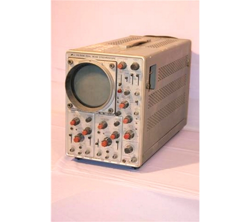
The dual-beam synchroscope or analog oscilloscope can display two signals simultaneously. Although multi-trace analog oscilloscopes can simulate a dual-beam display with chop and alternate sweeps, those features do not provide simultaneous displays. (Real time digital oscilloscopes offer the same benefits of a dual-beam oscilloscope, but they do not require a dual-beam display). This can be applied in various technological areas:
¢ In (electronics); it is a cathode-ray oscilloscope designed to show a short-duration pulse by using a fast sweep that is synchronized with the pulse signal to be observed.
¢ In (engineering); it is an instrument for indicating whether two periodic quantities are synchronous.
The Braun tube was known in 1897, and in 1899 Jonathan Zenneck equipped it with beam-forming plates and a magnetic field for sweeping the trace. Early cathode ray tubes had been applied experimentally to laboratory measurements as early as the 1920s, but suffered from poor stability of the vacuum and the cathode emitters. V. K. Zworykin described a permanently sealed, high-vacuum cathode ray tube with a thermionic emitter in 1931. This stable and reproducible component allowed General Radio to manufacture an oscilloscope that was usable outside a laboratory setting. After World War II surplus electronic parts became the basis of revival of Heathkit Corporation, and a $50 oscilloscope kit made from such parts was a first market success.
Rectifier
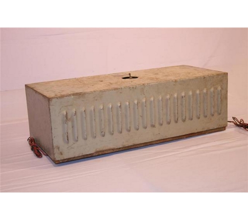
A rectifier is an electrical device that converts alternating current (AC), which periodically reverses direction, to direct current (DC), which flows in only one direction. The process is known as rectification. Physically, rectifiers take a number of forms, including vacuum tube diodes, mercury-arc valves, solid-state diodes, silicon-controlled rectifiers and other silicon-based semiconductor switches. Rectifiers have many uses, but are often found serving as components of DC power supplies and high-voltage direct current power transmission systems. Rectification may serve in roles other than to generate direct current for use as a source of power. German physicist Ferdinand Braun, a 24-year old graduate of the University of Berlin, studied the characteristics of electrolytes and crystals that conduct electricity at Würzburg University in 1874. Braun demonstrated this semiconductor device to an audience at Leipzig on November 14, 1876, but it found no useful application until the advent of radio in the early 1900s when it was used as the signal detector in a "crystal radio" set.
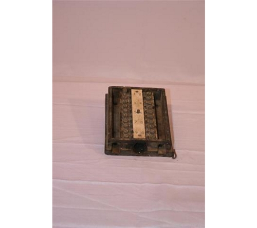
Sine Square Generator
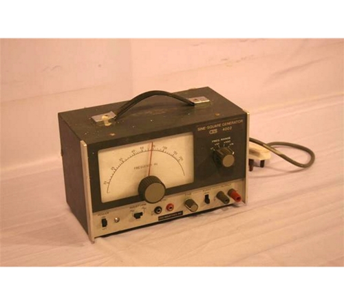
This is a compact yet versatile signal generator that can generate sine and square wave signals of more than 50 KHz. A signal generator is a device which produces simple repetitive waveforms. Such devices contain an electronic oscillator, a circuit that is capable of creating a repetitive waveform. The signal generator operates over four overlapping frequency ranges: 10 to 200 Hz, 100 Hz to 2 KHz, 1 to 20KHz, and 2 to 50 KHz, and within each of these ranges, the desired frequency is fully adjustable. Function generators are used in the development, test and repair of electronic equipment. For example, they may be used as a signal source to test amplifiers or to introduce an error signal into a control loop. By the early 1920s basic circuits for sine-, square-, and sawtooth-wave generators had been invented.
GEC Communication Receiver
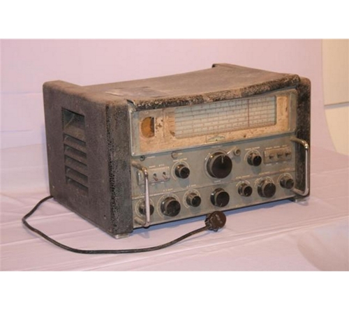
A GEC (General Electric Company) Communication Receiver is a model of a communications receiver used as a component of a radio communication link. Typically, a communications receiver is of the super heterodyne type in double, triple or, more rarely, quad conversion. It features multiple RF and IF amplification stages and may have at least one IF stage that is crystal controlled. It usually has a BFO and a product detector for SSB and CW reception. An example is the G.E.C. Communications Receiver Model BRT400, a very much sought after communication receiver, which uses 14 tubes (valves) was first produced in England in 1947, by the General Electric Company. It was designed to be a general purpose communication receiver which would give excellent results, over what was back in 1947, stated to be a wide range of frequencies.
Oscilloscope TF 1159
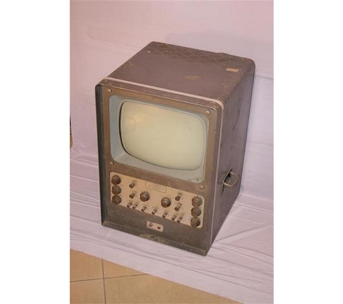
Oscilloscope TF 1159 is a model of an oscilloscope which is a laboratory instrument commonly used to display and analyse the waveform of electronic signals. In effect, the device draws a graph of the instantaneous signal voltage as a function of time. A typical oscilloscope can display alternating current (AC) or pulsating direct current (DC) waveforms having a frequency as low as approximately 1 hertz (Hz) or as high as several megahertz (MHz). High-end oscilloscopes can display signals having frequencies up to several hundred gigahertz (GHz).
i. Oscillograms and Oscillographs
Hand-drawing "oscillograms" according to galvanometer readings was the earliest method for picturing electrical waveforms. In 1880, Jules Francois Joubert invented the "point to point" stroboscopic contact method that allowed mechanisms, such as the 1903 Hospitalier Ondograph, to partially automate the process. Sometimes these partially automated pictures were called "oscillographs."
ii. Mirror Galvanometers
In 1826, Johann Poggendorff invented the mirror galvanometer, also known as the moving-coil meter, a device popularized in part by Lord Kelvin. Mirror galvanometers registered electrical quantities and moved light rays in response. Near the start of the 20th century, William Duddell developed a commercial version of the mirror galvanometer; accessories from the budding photography arts were able to record the light rays his devices signalled. Duddell-style instruments were so helpful that they were used all the way through the Second World War and beyond.
iii. Cathode Ray Tube
Because oscillograms, oscillographs and mirror galvanometers displayed voltages too slowly, inventors, seeking faster technologies, experimented with mercury jets, hot-wire and more. It was the cathode ray tube (CRT), initially suggested as a solution by Albert Hess and Ferdinand Braun in the 1890s, that proved to be the path forward. Compared to previous equipment, CRTs allowed for better and more efficient voltage images. It wasn't until the widespread adoption of CRTs in the 1920s that CRT oscilloscopes became practical, however.
iv. CRT Oscilloscopes
Varieties of CRT oscilloscopes proliferated throughout the 20th century, while engineers continually tinkered with CRT oscilloscopes. In 1946, Howard Vollum and Jack Murdock solved the problem of displaying repeating waveforms in a stationary and legible way by inventing the triggered oscilloscope, which took advantage of the phosphor screen. The pair went on to found Tektronix, which became a leading CRT oscilloscope manufacturer. In the 1970s, the company produced the first oscilloscopes that used direct-view bistable storage tubes, and, as a result, engineers could see single-pulse waveforms. Meanwhile, the oscilloscope had become a widely recognized emblem of technology: The Outer Limits, a 1960s science fiction television show, showed oscilloscope traces on its title screen.
v. Digital Oscilloscopes
In 1985, the LeCroy Corporation introduced the first digital oscilloscope, a computerized version of the analog machine. Digital oscilloscopes in the 21st century use digital memory and complex digital signal processing technologies to visually represent voltages in sophisticated ways, such as via commonplace printers. Oscilloscope software is now readily available for everyday home computers, and attempts at further innovations target such areas as wireless networking.
Wall (DP) Distribution Point
A point within a network where the cable or fibre terminates. This point provides a point of entry for engineers to terminate or test the network. This was used in the late 1890s for terminating of telephone cables or fibres.
Punner
A Punner is made of an iron or a cast-iron with fibreglass or metal handle. That is, it used for consolidating earth, hardcore and tarmac, particularly useful for tampering around lighting columns and telegraph poles. This was first used in the late 1890s.
Ready Access Terminal
A distribution terminal commonly used with aerial cable. Frequently referred to as a boot. It is a ready access closure which is provided for communication cables of the type surrounded by an outer dielectric sheath and an electrically conductive shield. The closure further includes a frame structure having end brackets, a longitudinal strap and a longitudinal tie brace; the strap and brace joining the brackets. A model of this was invented by Amaya; Mauricio (Roselle, IL), The Patent Number application was filed on March 3, 1980. The cable has its insulating sheath and its grounding shield severed over a portion within the splice case so that access to the various cable pairs for branch out purposes is facilitated.
Tool Box
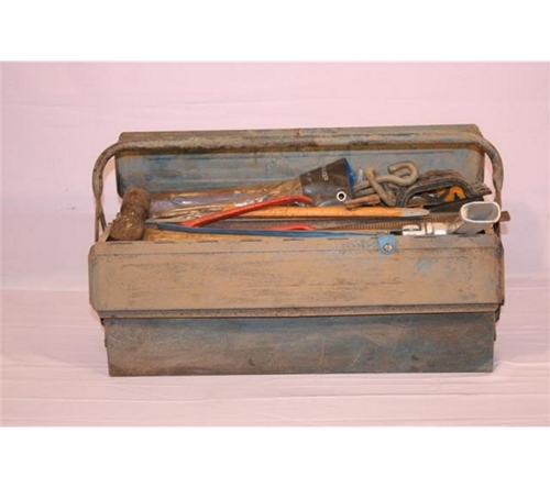
Telecom Tool Box is as old as the beginning of telecommunication from 1860s. Telecommunications refers to any technology that involves transmitting data over a distance. Phones, radios, cell phones, televisions, the Internet and wireless communication devices are all part of the telecommunications field. Before we can use these technologies, professionals must install lines and cables to make this happen, using a variety of tools including hand tools, cables and conductors (allow electricity to pass from one place to another). Other features of the tool box include a crimp tool, pliers, screwdrivers, tool pouch, blades and punch down tool, which allows you to create terminations and connect jumper wires.
Soldering Iron
A soldering iron is a hand tool used in soldering. It supplies heat to melt the solder so that it can flow into the joint between two work pieces. A soldering iron is composed of a heated metal tip and an insulated handle. Heating is often achieved electrically, by passing an electric current (supplied through an electrical cord or battery cables) through a resistive heating element. Soldering irons are most often used for installation, repairs, and limited production work in electronics assembly. High-volume production lines use other soldering methods. A lady invented soldering iron in ancient Egypt slightly over 5,800.But a German inventor Ernst Sachs patented the first electric soldering iron in 1921.
U Nails

"U" shaped nail is used for holding wire. It is a U-Shaped thin pointed piece of Metal that is hammered into materials as a fastener. This has been in use in the early 1850s.
Drilling Tool
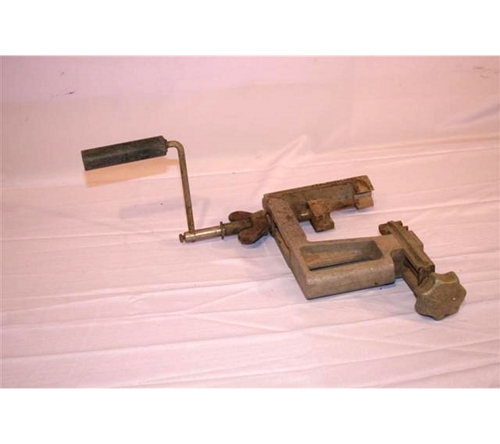
This is a tool used in drilling a hole and it can be defined as a rotary end cutting tool having one or more cutting lips, and having one or more helical or straight flutes for the passage of chips and the admission of a cutting fluid. This was first invented in 1805.
Hack Saw Handle
It is the frame in which the Hack Saw is mounted. A hacksaw is a handheld tool used to cut through materials like plastic tubing and metal pipes. Its cutting mechanism is provided by removable blades which feature sharp teeth along their outer edge. In most cases, a hacksaw consists of a metal frame that resembles a downward-facing U. The hacksaw was invented in ancient times, and the name of the inventor has long since been lost to history.
Safety Belt
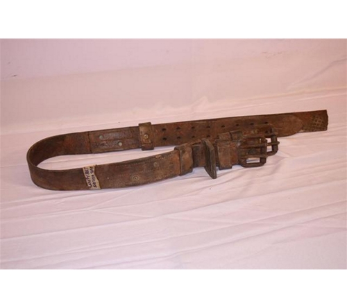
This is a belt or strap worn by a person working at a great height and attached to a fixed object to prevent him from falling. The safety belt was invented by a man named George Cayley. He first invented the lap belt or lap safety belt in the 1800s.
Mallet
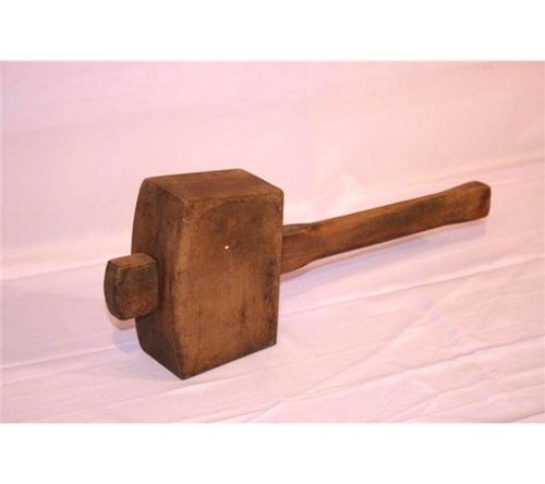
A mallet is a kind of hammer, usually of rubber, or sometimes wood smaller than a maul or beetle and usually with a relatively large head. An example of MALLET is Rubber mallets which are used when a softer blow is called for than that delivered by a metal hammer. They are typically used to form sheet metal, since they don't leave marks, as well as for forcing tight-fitting parts together, for shifting plasterboard into place, in upholstery, and a variety of other general purposes, including some toys. It is the most commonly used mallet. David A Geister of Prescott, Wisconsin, USA discovered the mallet in the early 1960's. He was working at 3M at the time.
Power Meters
These are meters used for measuring the amount of electric power used. Thus, it is an instrument for measuring the power of the electromagnetic oscillations generated by oscillators, amplifiers, radio transmitters, and other devices operating in the high-frequency, superhigh-frequency, or optical regions. Power meters may measure absorbed or transmitted power. Power meters are classified according to method of measurement as calorimetric, bolometric, thermoelectric, ponderomotive, and so on.
The kilowatt hour meter was designed in 1883 and was patented by Dr. Hermann Aron as a simple DC meter. The first DC power meter was introduced to the market in 1888 to be commercialized.
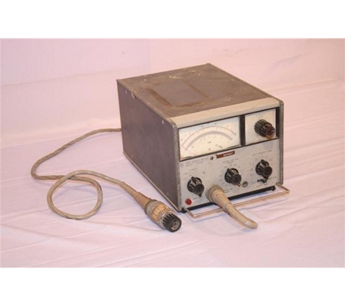
Associated Research (Grounding Ohm Meter)
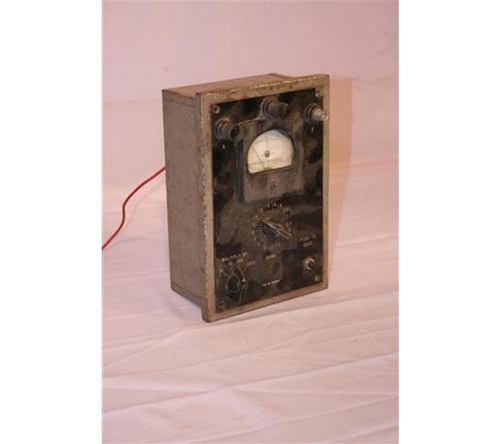
This Apparatus was used in the 1940s for testing grounding resistances. Grounding connections between apparatus or electrical circuits and the earth are very important. In some instances, grounding forms part of the circuit whereas, in other instances they do not normally carry appreciable current but merely serve as safety precautions (for example, to carry lightening charges to the ground). It is standard practice in telecommunications to specify a certain maximum ground resistance permissible for telecommunications equipment. By connecting this apparatus to the ground in series after providing a source voltage, the apparatus will give the reader the ground resistance which is influenced by the proximity of the water table levels to the conductor being used as part of the telecommunication equipment s circuit or connections, its dampness and density, etc.
Moving Coil Voltmeter
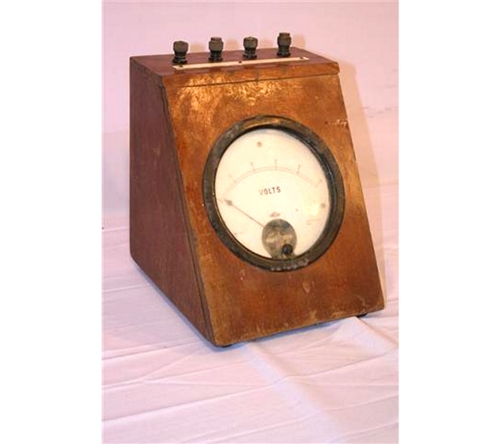
This is a voltmeter (also called galvanometer in some cases) in which the current, produced when the voltage to be measured is applied across a known resistance, is sent through coils pivoted in the magnetic field of permanent magnets, and the resulting torque on the coils is balanced by control springs so that the deflection of a pointer attached to the coils is proportional to the current. It is generally used in an analog Volt-ohm-milliammeter. Jacques-Arsène d'Arsonval (June 8, 1851 - December 13, 1940) a French biophysicist was the inventor of the moving-coil galvanometer also known as voltmeter. Another version had it that: The invention of the moving-coil galvanometer is credited to Johann Schweigger in 1825.
Universal AVO-Meter
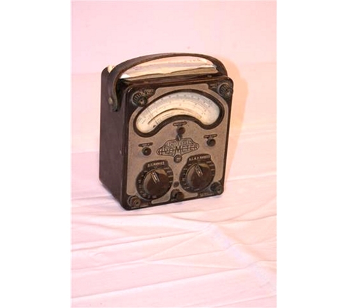
The Avometer was the world's first multimeter and was invented by the British Post Office engineer Donald Macadie in 1923. The Avometer was a British brand of multimeter, latterly owned by Megger. The most widespread of the range was the Model 8, which was produced in various versions from the 1950s until 2008, the last version being the Mark 7. It is often called simply an AVO and derives its name from the first letter of the words amperes, volts, ohms.
5MHz Transmission Test Trolley
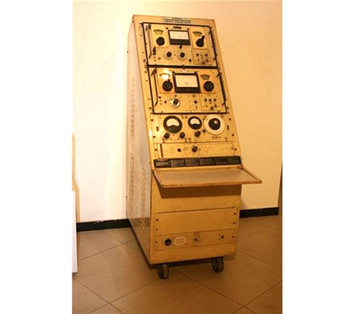
5mhz transmission test trolley first used in the early 1910s is an equipment test set which is a fully programmable instrument with a bandwidth of 5MHz. The 5MHz (60m) amateur allocation spans 5 fixed frequencies and requires a NoV from the RSGB. The 60 meter band or 5 MHz band is a relatively new (2002) amateur radio band that was originally only available in a few countries, such as the United States, United Kingdom, Norway, Finland, Denmark, Ireland and Iceland. In the last few years however, an increasing number of countries' telecommunications administrations - together with their government and military users - have permitted Amateur Radio operation in the 5 MHz area on a short or longer term basis on either discrete channels or a frequency band allocation.
Tester
This is also known as Line Tester used in the 1930s. Telecommunications devices are types of technology that are used to transmit data and sound, through cables. These devices sometimes develop problems, damage or glitches, so a variety of tools have been created to help telecommunications repair technicians locate the cause of the malfunction and apply the appropriate repairs. Thus, telecom line tester is used for line maintenance and construction. The tester incorporates the functions of a telephone set, a circuit performance tester and a security tester, which makes it a comprehensive device for detecting line errors. It can be used to dial and has function switches which enable the user to determine the device functions
Wireless Set HP 311 Sounder Receiver
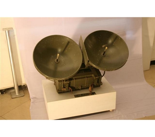
This is a model of a radio receiver for a sounder which is for the detection and measurement of phenomena linked with the earth's environment, wherein it comprises a reception channel, whereof one input receives the echo signals of the electromagnetic signals emitted towards the phenomenon. Another type of Sounder Receiver is the Oblique Sounder Receiver, this is a receiver used in analysis of the ionosphere to determine the best available frequency for a known path between two points on the earth s surface. Professor A. Slaby, inventor of the process of wireless telegraphy was one of the early inventors of sounder receiver in 1910s.
First Coin Box
This is a telephone that requires immediate payment for operation, as by a coin or credit card. Also called pay station. Pay telephone stations preceded the invention of the pay phone and existed as early as 1878. These stations were supervised by telephone company attendants or agents (such as an employee in a hotel where a station might be located) who collected the money due after people made their calls. In 1889, the first public coin telephone was installed by inventor William Gray at a bank in Hartford, Connecticut. It was a "postpay" machine (coins were deposited after the call was placed). In 1977, "automatic coin telephone service" was introduced in Phoenix, Ariz. This allowed most pay telephone calls, including long-distance, to be made without operator assistance.
1895's Line Corded Candle Stick Phone
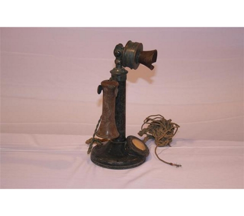
The candlestick telephone was manufactured from the early 1890s through the 1920s. The Candlestick phone without a dial, also known as the ˜Upright' initially became popular during the early 1900s and had many manufacturers before the introduction of the one-piece handset. The Crosley CR64 1-Line Corded Phone is one of the first Candlestick phones which were introduced when the magneto system was in use, which meant that the phone was connected to a large wooden box called a subset containing a battery, bell, and crank.
1905's Telephone
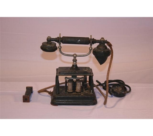
This 1905 s model of telephone was called a skeletal phone and sometimes called an Eiffel Tower phone by collectors; it has an important place in telephone history, as it was the world's first production handset telephone by L. M Ericsson and thus set a trend that the rest of the world followed. L. M Ericsson sold his parts to other companies so the phone is found in many varieties.
Some of the models have a brass fitting on the pillar to hold a card with the telephone number on it. Other options were gradually added to the range. Around 1900 a minor modification was made to the wiring to the bell motor. In the earlier models a wire was run from a small brass plate mounted on the deck just above the motor. Post 1900 models had this replaced with two metal straps running from screws mounted directly in the deck to the bell motor.
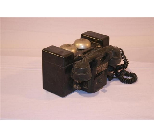
1920's Telephone
One of the most significant advancements in telephone communications in the 1920s was the advent of automated exchanges. Previously, people needed to contact an operator who would then connect the call. Automated exchanges allowed for personalised numbers to be dialled from home and directly connected. This advancement was made possible by improvements to the transmitters and telephone design.
1924's Telephone
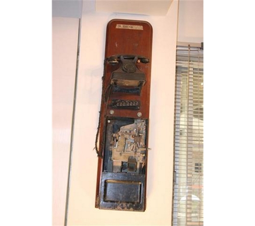
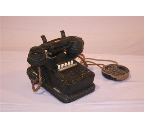
The GPO 121F WALL TELEPHONES are some of the models of 1924. There is the wall version of GPO model 150 Telephone. Made originally from the Bell set No1 Item A1089.
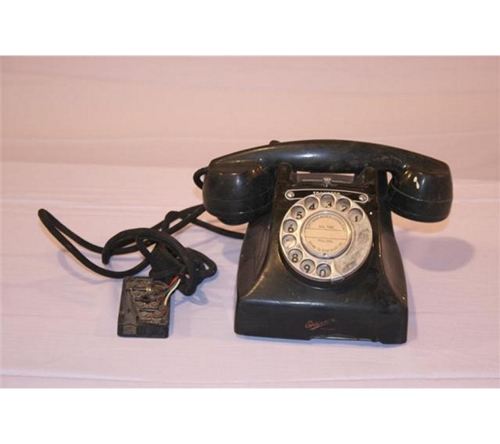
1930's Rotary Dial Telephone
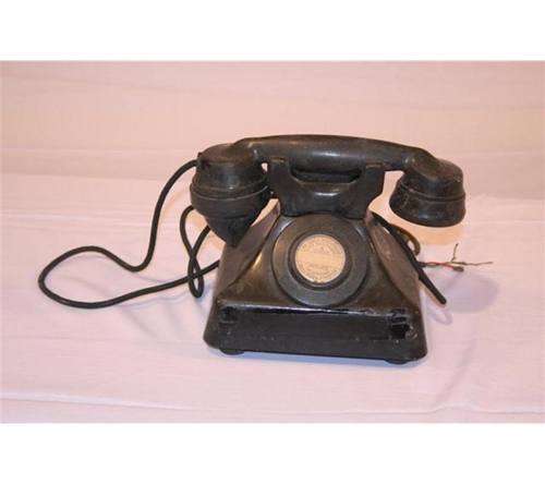
Rotary dial phones are the earliest user controlled phone to be mass produced. : Rotary telephones work on a pulse system. Prior to the rotary phone, a user would pick up the phone, wait for the operator to answer and then tell the operator who they wanted to be connected with. With the rotary dial, the user was able to dial freely, allowing for quicker and more convenient connection to the people they wanted to speak with. In 1937, Western Electric and the Bell System introduced the model 302 rotary dial phone, created by the renowned industrial designer, Henry Dreyfuss. The shell of the 302 was intended to be cast out of metal. However, in 1941, the critical war-time need for metal caused Western Electric to retool to make the 302 out of molded thermoplastic. The 302 was the first telephone containing all of its circuitry within the base and not requiring a separately mounted apparatus box for the ringer.
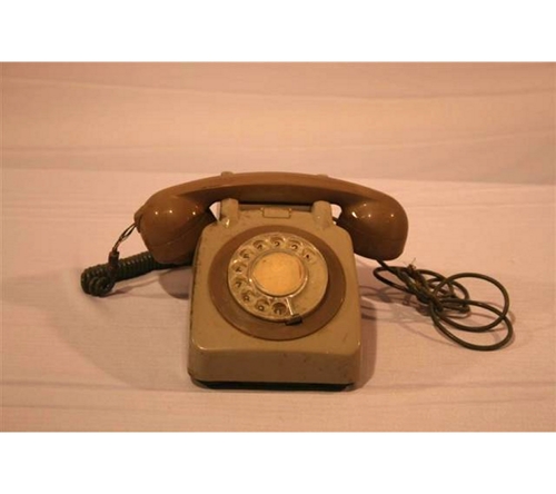
1940's Rotary Dial Telephone
The rotary dial is a device mounted on or in a telephone or switchboard that is designed to send electrical pulses, known as pulse dialing, corresponding to the number dialed. The early form of the rotary dial used lugs on a finger plate instead of holes. Almon Brown Strowger filed the first patent for a rotary dial, U.S. patent #486,909, on December 21, 1891, that was later issued to him on November 29, 1892. The modern version of the rotary dial with holes was first introduced in 1904 but did not enter service in the Bell System until 1919. The rotary dial was gradually supplanted by Dual-tone multi-frequency pushbutton dialing, introduced at the 1962 World's Fair, which uses a keypad instead of a dial. Some telephone systems in the US no longer recognize rotary dialing by default, but will only support push-button phones.
The standard form of the rotary dial is a disk three inches in diameter with 10 holes, numbered in one of four forms 1-9 then 0, 0-9, 9-0 or 0 then 9-1. Despite the different numberings, when the first number was dialed, 1 pulse was sent and when the last number was dialed, 10 pulses. This meant that each phone on a system had to have the same dial and phones could not be easily interchanged into other systems. The 1-9 then 0 form was eventually standardized.
1980's Rotary Dial, Push Button and Touch Tone Telephone
The rotary telephone assisted the user to complete other tasks while talking on the phone. Between 1930 and 1980, the rotary phone became more convenient to use and less awkward. In the 1980s, push button phones began production; however, you could still find rotary phone in many homes. Since the 1990s, rotary telephones have slowly disappeared from homes. Also, the touch tone telephone is a communication device that makes use of a form of telephone switching or the connecting of a call from one phone to another that is known as dual-tone multi-frequency (DTMF). DTMF replaced the earlier pulse style of switching that was common with the rotary dial phones commonly used through the 1970s. A simple telephone keypad replaced the rotary dial on the newer touch tone telephone units that became the industry standard for both cell phones and land lines.
The development of touch tone services began in the middle of the 20th century, and touch tone telephones were first introduced to a wide sector of the consumer market in the early 1970s. The basic process of the new tone dialing made it possible to switch calls with more efficiency. It also created the means of using specific tones to access a range of ancillary services that were not possible with the traditional pulse signal.
With the invention of push button, touch tone, wireless and cell phones, rotary telephones became all but obsolete.